Terminologies
| Terminology | Description |
|---|---|
| Collection | Folder storing an asset’s data on Akselos Cloud or locally |
| Components | Modules generated through componentization for use with Integra |
| Model ribbon | Toolbar with model‑building and management tools |
| Ribbons | Top toolbars in Akselos Modeler |
| Property Tree | Left‑bottom panel showing selected items’ properties |
1. Introduction
This article explains how to set up cross-sections for one-dimensional stiffeners in an Akselos model for floating offshore wind turbine applications. The focus is on defining, assigning, orienting, and offsetting one-dimensional stiffeners so that their structural contribution is represented consistently within a reduced-order structural model.

What you will learn with this tutorial:
- Creating & defining cross-section profiles.
- Assigning Cross-section to 1D stiffener subdomain.
- Rotating and offsetting 1D cross-section.
What is the stiffener?
In offshore structural design, a stiffener is a structural member attached to shell plating to increase stiffness, improve load-carrying capacity, and control deformation. Stiffeners are commonly used on columns, pontoons, and braces to enhance bending and buckling resistance without significantly increasing structural weight.

Figure 1.1: Stiffeners in a real structure
Why is a 1D stiffener used in the floating offshore wind turbine simulation model?
In a floating offshore wind turbine simulation model, the primary objective is to capture the global structural response efficiently while maintaining sufficient accuracy. Representing stiffeners as 1D elements allows their stiffness and mass contributions to be included without explicitly modeling detailed 2D shell geometry or full 3D solid representations. This approach reduces computational cost and model complexity while remaining suitable for global strength, inertia relief, and coupled load-response analyses.

Figure 1.2: Akselos FOWT model modeled with 2D stiffener (left) and 1D stiffener (right)
1D stiffener in Akselos
In Akselos, 1D stiffeners are modeled using beam elements associated with 2D shell subdomains. Their structural behavior is defined through assigned cross-sections, material properties, orientation, and offset relative to the shell mid-surface. When configured correctly, these 1D elements contribute to the overall stiffness and mass of the structure and interact consistently with 2D shell elements within the reduced-order solver framework.
This section provides the conceptual background required before configuring cross-sections and assigning them to 1D stiffeners in subsequent steps.
2. Before we start
Before configuring cross-sections for 1D stiffeners, access to the required Akselos tools and a suitable baseline model must be in place. The workflow relies on authenticated access to the Akselos Portal, availability of Akselos Modeler, and a pre-prepared reference collection. Ensuring these elements are ready avoids interruptions during the setup process.
2.1 Access and Authentication
To follow the instructions in this tutorial, access to the required Akselos tools and reference data is mandatory.
Akselos Portal account
A valid Akselos account is required to sign in to the Akselos Portal. Portal access allows users to access collections, download sample data and software installers, and connect with Akselos Modeler.
- Install Akselos Modeler
Akselos Modeler is the simulation software used throughout this tutorial. After download and install, authentication the software with your Akselos Portal account is required to import sample collections and data and to open models in Akselos Modeler.
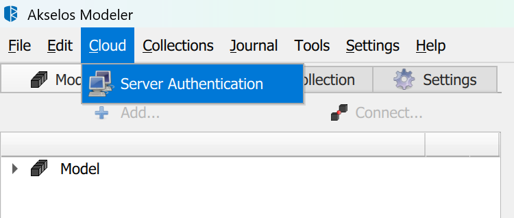
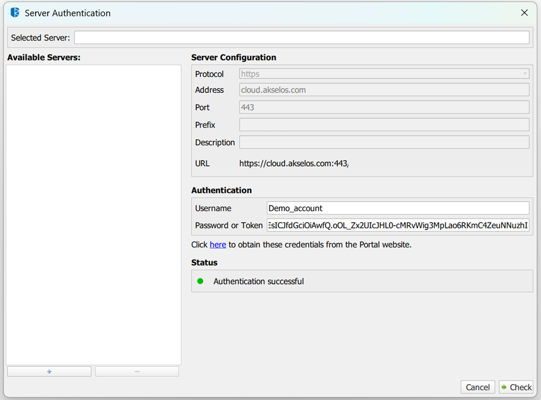
Figure 2.1: Checking authentication
Sample collection
A reference sample collection is provided for this tutorial. After authentication, import the DCW 5MW tutorial 1 sample collection from the Akselos Portal and open it in Akselos Modeler.
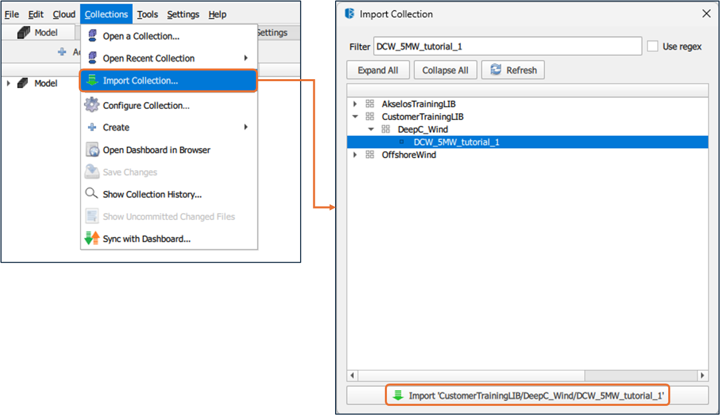
Figure 2.2: Importing collection - DCW_5MW_tutorial_1
Ensure that authentication is completed and that access to the sample collection is confirmed before proceeding with the implementation steps. For access requests or assistance, contact [email protected]
2.2 Modeling Assumptions
The following assumptions apply to the setup described in this article:
The global structure is primarily represented using 2D shell elements for plating and 1D beam elements for stiffeners.
The model is intended for capturing global structural response, not detailed local stress concentrations.
Structural behavior is evaluated within a reduced-order framework suitable for coupled load-response analysis.
2.3 Prerequisites
Before starting the cross-section setup, verify that the following conditions are met:
Shell subdomains representing the main structural components are already created.
1D stiffener geometry exists and is correctly connected to the corresponding 2D shell elements.
Material definitions required for shells and stiffeners are available in the model.
Users are familiar with navigating the Model ribbon, Property Tree, and selection modes in Akselos Modeler.
Once these conditions are satisfied, the model is ready for cross-section creation and assignment, as described in the next section.
3. Implementation
Execute the operational sequence below to fully configure the 1D stiffener elements within the structural twin. This workflow transitions from abstract parameter definition to specific geometric adjustments on the mesh.
STEP 1: Define Cross-Sections
Parametric profiles for stiffeners must be defined in the Collection to ensure consistent physical properties across the model. Centralizing these definitions allows for efficient mass and inertia management without redundant manual entry for every beam.
Akselos Modeler provides a Cross-section library that allows users to define multiple cross-section types and reuse them across different parts of a collection.
How to:
- Navigate to the Collection panel on the left interface.
- Locate CrossSectionGroup_1, right-click it, and select Add Property→ Crosssectiongroupitem.
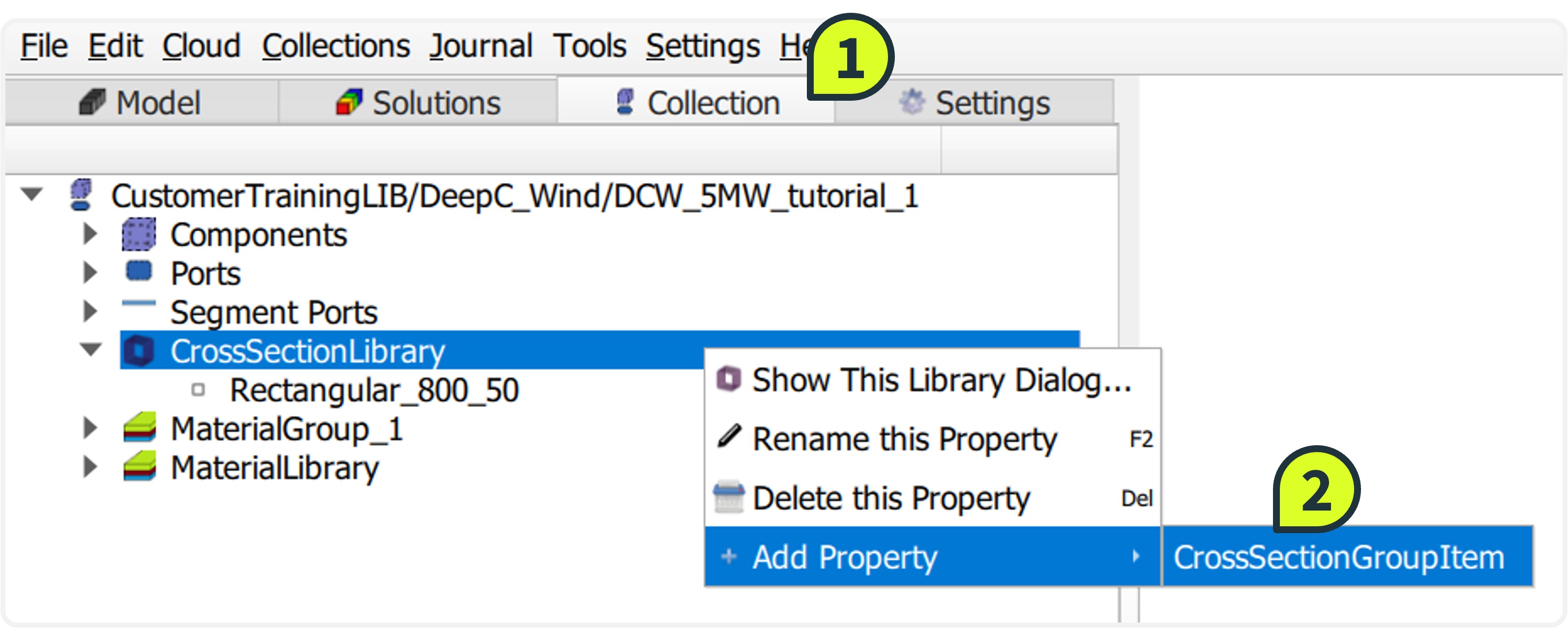
- Select the newly created item (default name CrossSection 1). Right-click to Rename it to Rectangular_800_50_new.
- In the Property Tree, locate the value field and change the cross_section type to RectangularCrossSection. Input the following dimensions into the parameter fields:
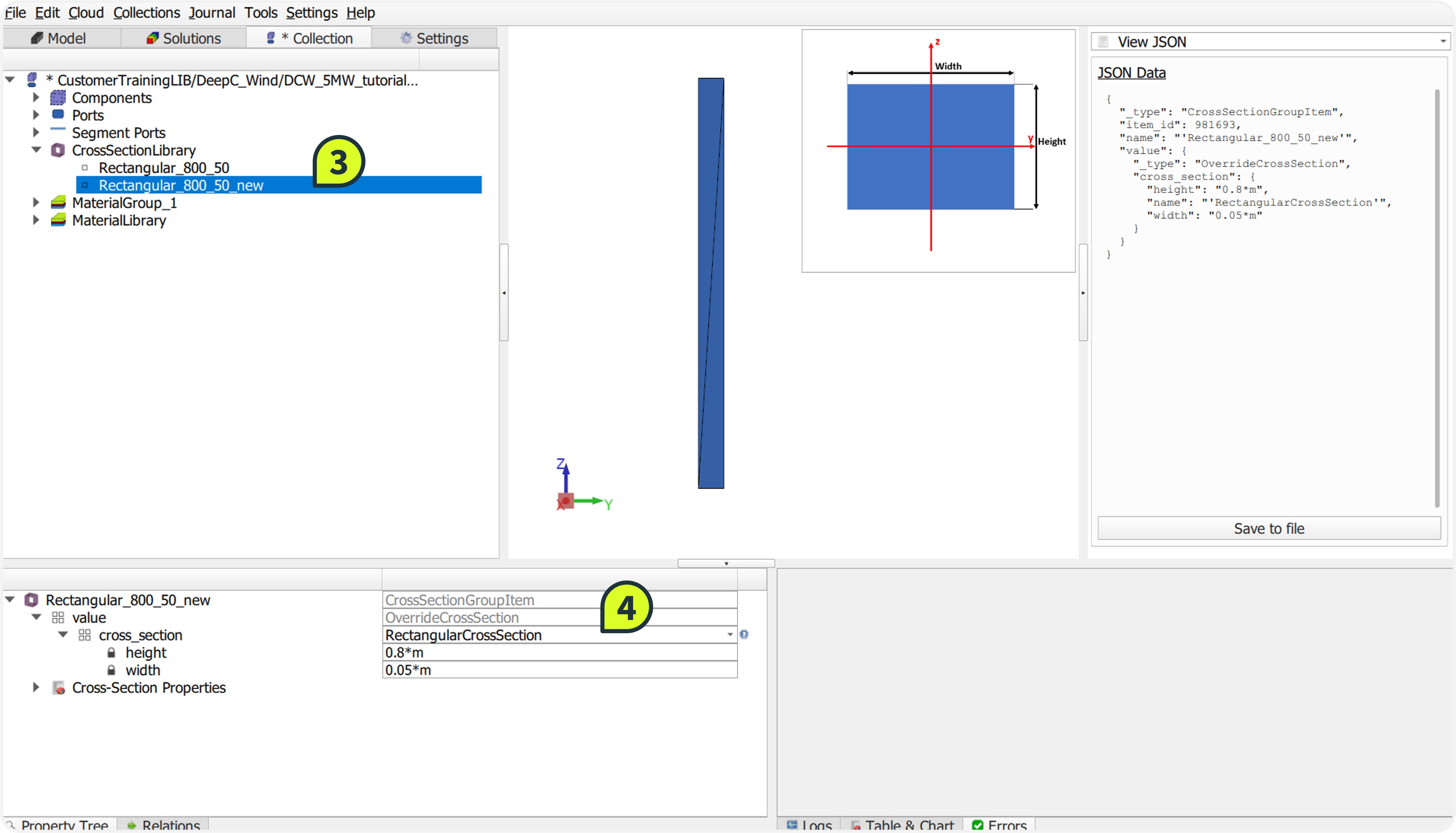
- height:0.8*m
- width:0.05*m.
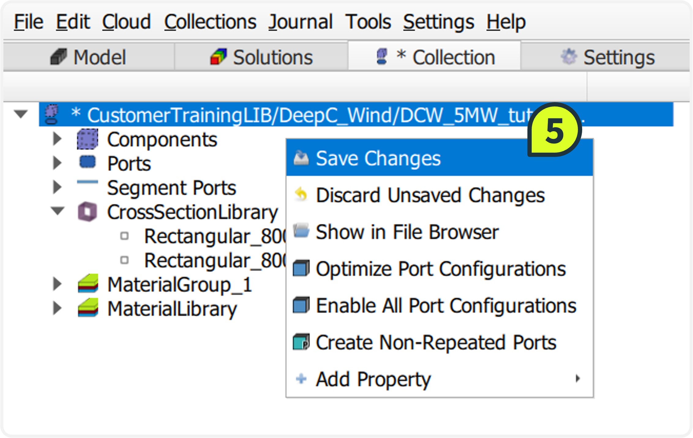
- Right-click the collection name in the Collection panel and select Save Changes to persist the new definition.
STEP 2: Assign Properties
Mapping the logical cross-section definitions to physical mesh lines is required to initialize the component. This action links the geometric parameters created in the previous step to the specific subdomains representing the ring and longitudinal stiffeners.
How to:
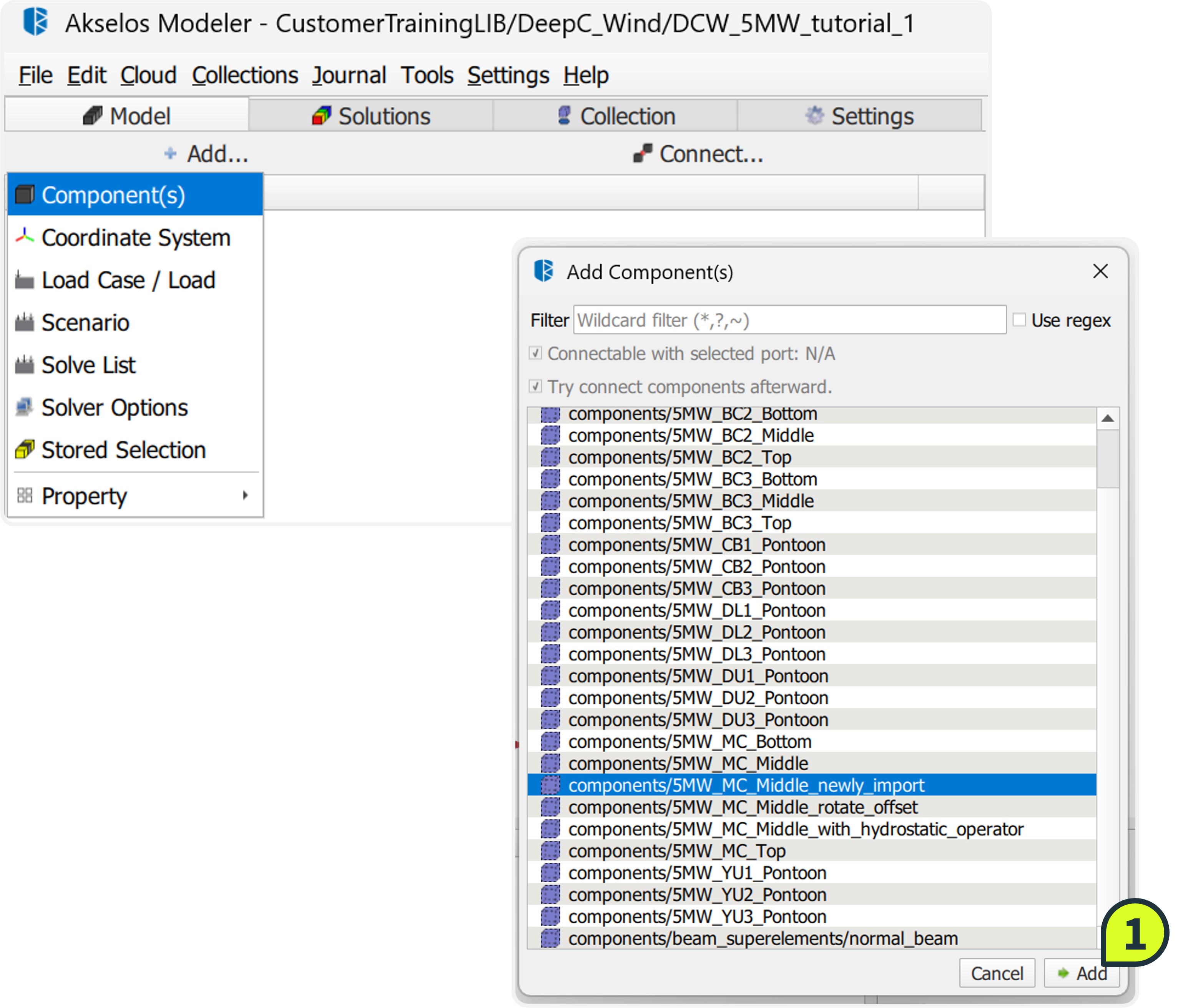
Click Add → Components(s), select components/5MW_MC_Middle_newly_import, and click Add.
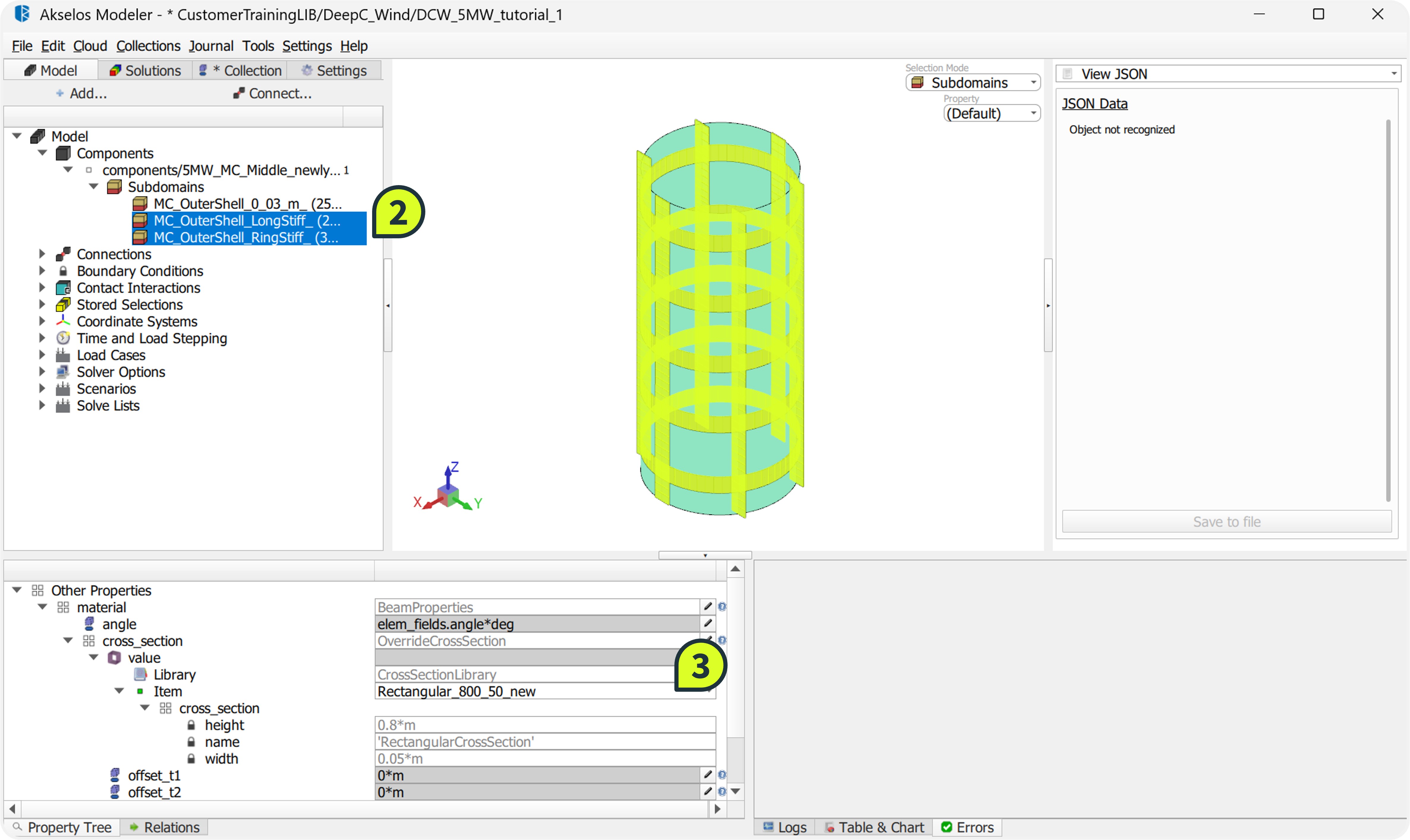
In the Subdomains list, hold Ctrl to select both:
MC_OuterShell_LongStiff_ (longitudinal stiffeners)
MC_OuterShell_RingStiff_ (ring stiffeners)
Navigate to Property Tree → Material → cross_section → Value. Select Rectangular_800_50_new from the dropdown list.
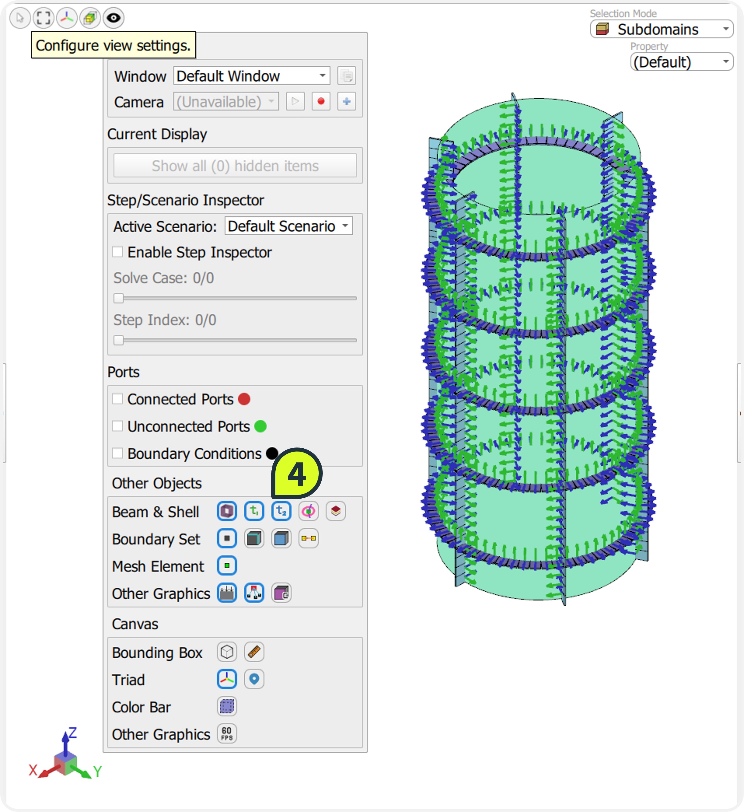
To verify the assignment, open Configure view settings (eye icon) and enable Show Beam Cross-section, Show local t1-axis and t2-axis
STEP 3: Rotate Stiffeners
Aligning the beam's local coordinate system (t1, t2) with the shell surface is essential for accurate structural response. There are two distinct methods to perform this rotation in Akselos Modeler:
Numerical rotation: Directly inputting a rotation angle in the Property Tree.
Geometric orientation: Using the Orient Tool to align the beam axis relative to a reference vector.
In this workflow, both methods are used to demonstrate their application.
How to:
Method 1: Numerical Rotation (Applied to Ring Stiffeners)
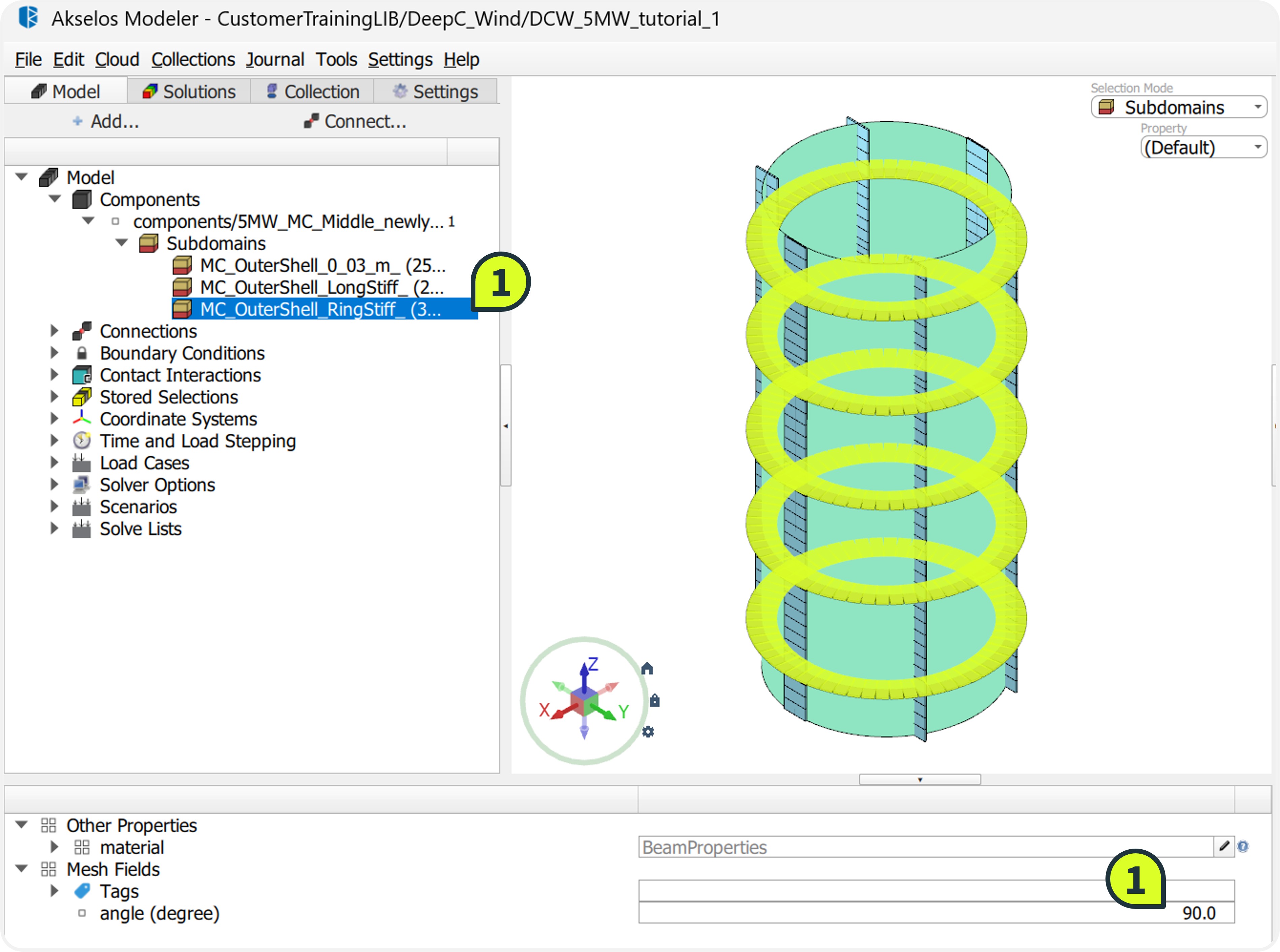
Select the ring stiffener subdomain MC_OuterShell_RingStiff_.
Navigate to the Property Tree and locate the angle (degree) field.
Enter a value of 90.
Verify in the Graphic Window that the ring stiffeners are now perpendicular to the outer shell.
Method 2: Geometric Orientation (Applied to Longitudinal Stiffeners)
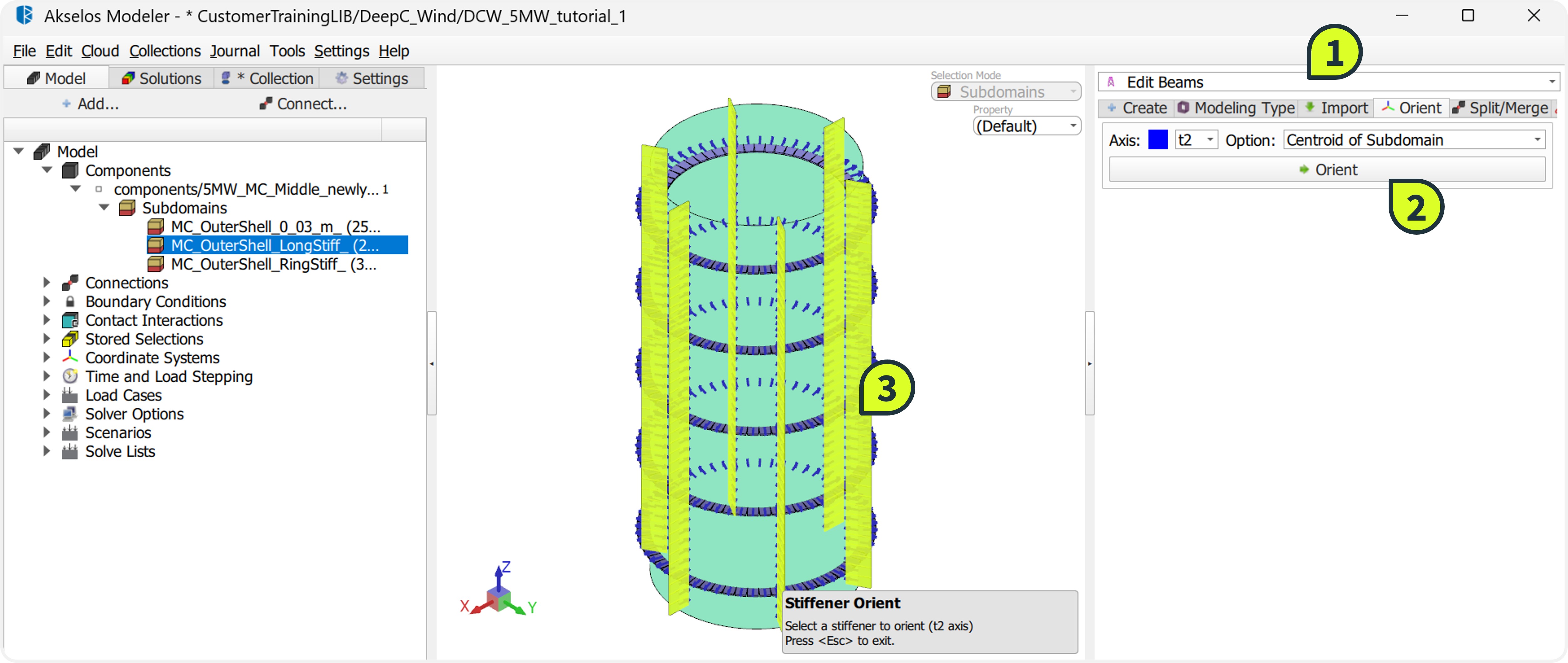
Open the Edit Beams tool located on the right ribbon.
Select the Orient tab.
Configure the alignment parameters:
Axis: Select t2 (aligns the vertical axis of the cross-section).
Options: Select Center of Subdomain (aligns relative to the subdomain center).
Click the Orient button.
In the Graphic Window, click on the MC_OuterShell_LongStiff_ subdomain to apply the geometric rotation.
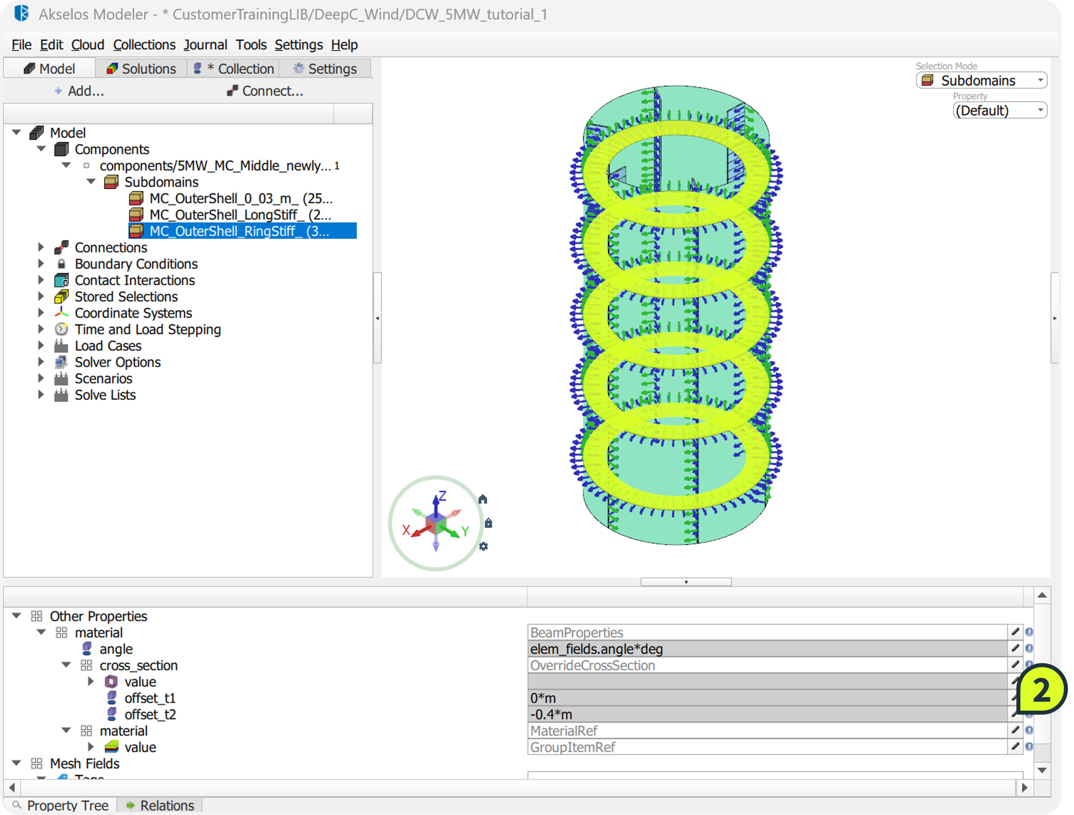
STEP 4: Offset Stiffeners
To simulate the physical weld location accurately, the beam elements must be shifted from their centroid. This geometric offset ensures the stiffeners sit flush against the outer shell surface rather than intersecting the plate, preventing overlaps in the stiffness matrix.
How to:
- For Ring Stiffeners:
- Select MC_OuterShell_RingStiff_.
- In the Property Tree, locate the offset_t2 field and input -0.4.
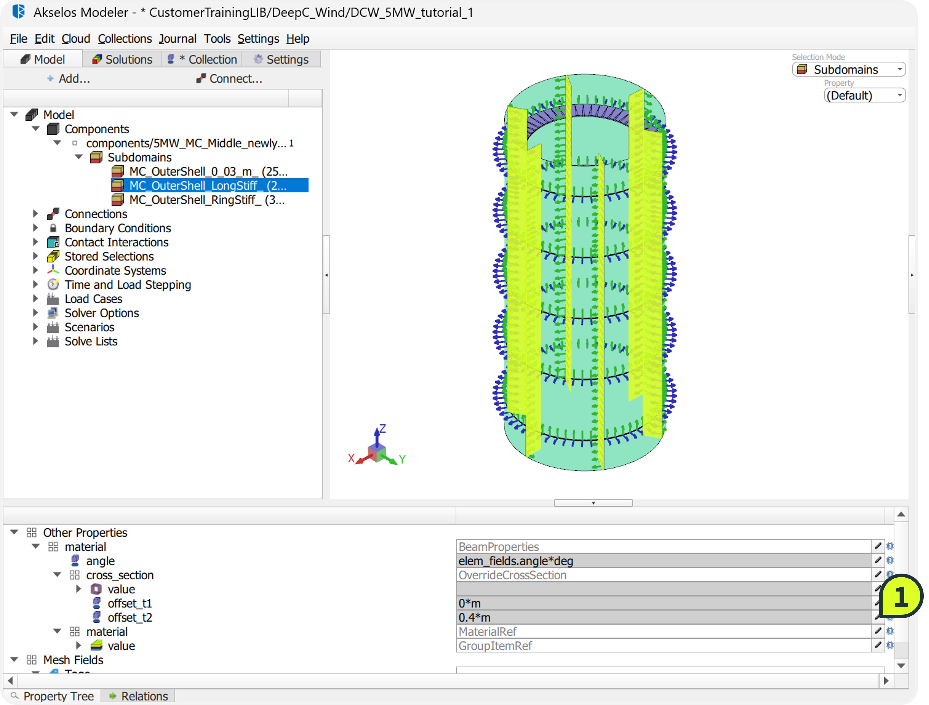
- For Longitudinal Stiffeners:
- Select MC_OuterShell_LongStiff_.
- In the Property Tree, locate the offset_t2 field and input 0.4.
- Verify the final configuration by comparing it with the reference component 5MW_MC_Middle_rotate_offset (if available in the library).
- Navigate to Collection ribbon, right-click the component 5MW_MC_Middle_newly_import in the structure tree and select Save Changes.